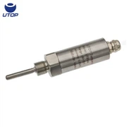

What Details Should Be Considered When Installing a Level Transmitter
Jan 05, 2026
I. General Preparations Before Installation
1. Verify Process Compatibility
Medium type (water, oil, acids/alkalis, slurries?)
Are temperature and pressure ranges within the transmitter's permissible limits?
Are there special requirements such as explosion-proof, sanitary, or corrosion-resistant (Hastelloy/PTFE) specifications?
2. Inspect Installation Location
Avoid locations near inlet ports, outlet ports, agitators, or areas prone to bubble concentration.
Select a position where the liquid surface is stable and free from turbulence.
II. Installation Details
1. Immersion-Type Level Transmitter (Static Pressure Type)
Vertical Suspension:
Must be vertically submerged to the bottom of the liquid. Do not suspend at an angle or against the wall, as lateral forces on the diaphragm may cause damage.
Mounting Method:
Use dedicated suspension cable + counterweight to avoid cable load-bearing (cable is solely for signal transmission).
Vent Protection:
The cable contains a vent tube to equalize atmospheric pressure. The vent end must remain dry and free from blockage (install desiccant or a breather).
Surge/Lightning Protection:
For outdoor installations, add a lightning protection module and ground the cable through a metal conduit.
Depth Allowance:
The diaphragm should be positioned below the low liquid level, but avoid contact with sludge or sediment.
Never connect the vent tube to a sealed pipe or positive-pressure environment!
2. Flanged/Threaded Level Transmitter (Static Pressure or Differential Pressure)
Diaphragm Orientation:
The diaphragm must contact the medium; do not install it facing upward (gas accumulation causes measurement distortion).
Sealing:
Use appropriate gaskets (e.g., PTFE, graphite). Threaded connections require PTFE tape, but avoid contaminating the diaphragm.
Torque Control :
Tighten per manufacturer's specifications (typically 20–40 N·m). Excessive torque may damage the diaphragm.
Drain/Flush Port:
Install a drain valve at the bottom for easier maintenance and cleaning.
3. Differential Pressure Level Transmitter (with Capillary Remote Transmission)
Capillary Protection:
Avoid bending (minimum bending radius ≥50 mm), crushing, or high-temperature baking.
Dual Flange Level Alignment:
Positive and negative pressure sides must have flanges at the same horizontal level; otherwise, zero-point error will occur.
Filling Fluid Matching:
Select silicone oil type based on medium temperature (e.g., 300°C silicone oil for high temperatures).
Installation Orientation:
Position the transmitter body as close as possible to the high-pressure side to minimize capillary length differences.
III. General Electrical Installation Guidelines
Power Supply and Load Matching: Two-wire 4–20 mA loop: Ensure power supply ≥12V + 0.02V × R (typically R ≤600Ω).
Shielding and Grounding: Use shielded twisted-pair cable with shield grounded at one end (typically at the control room side) to prevent ground loop interference.
HART Communication Requirements: The loop must contain ≥250 Ω resistance (additional resistor required if PLC input impedance is insufficient).
Explosion-Proof Zone Wiring: Use flameproof/intrinsically safe certified junction boxes with cable seals compliant with Ex requirements.
IV. Mandatory Post-Installation Procedures
Power-Up Warm-Up: Some smart transmitters require 5–10 minutes for stabilization.
Zero Calibration: Execute "Zero Trim" with empty tank (or known liquid level).
Function Test: Fill/drain tank and observe linear output response.
Record Parameters: Save range, damping, and other configurations for future maintenance.
For details, please contact Qi Huang: qihuang@utopsensor.com