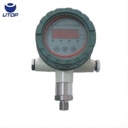

Fault Debugging Steps for A Differential Pressure Transmitter
Sep 19, 2022
Fault debugging steps for our UPB5 differential pressure transmitter are as follows:
1. Check the power supply
a) whether the positive and negative poles of the power supply are connected correctly or not.
b) whether the power supply of the transmitter has 24V DC voltage; it must be ensured that the power supply voltage supplied to the transmitter is greater than or equal to 12V (that is, the voltage at the input terminal of the transmitter power supply is greater than or equal to 12V).
2. If there is no power supply
a) check whether the circuit is disconnected or not.
b) check whether the detection instrument is selected incorrectly (input impedance should be ≤250Ω) and so on.
3. If the pressure transmitter has a meter head, it is necessary to check whether the meter head is damaged. If the meter head is damaged, The header needs to be replaced.
4. If there is a problem with the differential pressure pressure transmitter, you can connect the ammeter in series with the 24V power circuit to check whether the current is normal. If it is normal, it means that the transmitter is normal. At this time, you should check whether other instruments in the loop are normal.
For more details, please contact Stella Meng.